Leonardo
Leonardo is the pre-exascale Tier-0 supercomputer of the EuroHPC Joint Undertaking (JU), hosted by CINECA and currently located at the Bologna DAMA-Technopole in Italy. This guide provides specific information about the Leonardo cluster, including details that differ from the general behavior described in the broader HPC Clusters section.
Access to the System
The machine is reachable via ssh (secure Shell) protocol at hostname point: login.leonardo.cineca.it.
The connection is established, automatically, to one of the available login nodes. It is possible to connect to Leonardo using one the specific login hostname points:
login01-ext.leonardo.cineca.it
login02-ext.leonardo.cineca.it
login05-ext.leonardo.cineca.it
login07-ext.leonardo.cineca.it
Warning
The mandatory access to Leonardo si the two-factor authetication (2FA). Get more information at section Access to the Systems.
System Architecture
The cluster, supplied by EVIDEN ATOS, is based on two new specifically-designed compute blades, which are available throught two distinc Slurm partitios on the Cluster:
X2135 GPU blade based on NVIDIA Ampere A100-64 accelerators - Booster partition.
X2140 CPU-only blade based on Intel Sapphire Rapids processors - Data Centric General Purpose (DCGP) partition.
The overall system architecture uses NVIDIA Mellanox InfiniBand High Data Rate (HDR) connectivity, with smart in-network computing acceleration engines that enable extremely low latency and high data throughput to provide the highest AI and HPC application performance and scalability.
The Booster partition entered pre-production in May 2023 and moved to full production in July 2023. The DCGP partition followed, starting pre-production in January 2024 and reaching full production in February 2024.
Hardware Details
Type |
Specific |
|---|---|
Models |
Atos BullSequana X2135, Da Vinci single-node GPU |
Racks |
116 |
Nodes |
3456 |
Processors/node |
|
CPU/node |
32 |
Accelerators/node |
4x NVIDIA Ampere100 custom, 64GiB HBM2e NVLink 3.0 (200 GB/s) |
Local Storage/node (tmfs) |
(none) |
RAM/node |
512 GiB DDR4 3200 MHz |
Rmax |
241.2 PFlop/s (top500) |
Internal Network |
200 Gbps NVIDIA Mellanox HDR InfiniBand - Dragonfly+ Topology |
Storage (raw capacity) |
106 PiB based on DDN ES7990X and Hard Drive Disks (Capacity Tier) 5.7 PiB based on DDN ES400NVX2 and Solid State Drives (Fast Tier) |
Type |
Specific |
|---|---|
Models |
Atos BullSequana X2140 three-node CPU blade |
Racks |
22 |
Nodes |
1536 |
Processors/node |
|
CPU/node |
112 cores/node |
Accelerators |
(none) |
Local Storage/node (tmfs) |
3 TiB |
RAM/node |
512(8x64) GiB DDR5 4800 MHz |
Rmax |
7.84 PFlop/s (top500) |
Internal Network |
200 Gbps NVIDIA Mellanox HDR InfiniBand - Dragonfly+ Topology |
Storage (raw capacity) |
106 PiB based on DDN ES7990X and Hard Drive Disks (Capacity Tier) 5.7 PiB based on DDN ES400NVX2 and Solid State Drives (Fast Tier) |
File Systems and Data Management
The storage organization conforms to CINECA infrastructure. General information are reported in File Systems and Data Management section. In the following, only differences with respect to general behavior are listed and explained.
Warning
The backup service on the $HOME area is currently not active.
$TMPDIR
on the local SSD disks on login nodes (14 TB of capacity), mounted as
/scratch_local(TMPDIR=/scratch_local). This is a shared area with no quota, remove all the files once they are not requested anymore. A cleaning procedure will be enforced in case of improper use of the area.on the local SSD disks on the serial node (
lrd_all_serial, 14TB of capacity), managed via the Slurmjob_container/tmpfs plugin. This plugin provides a job-specific, private temporary file system space, with private instances of/tmpand/dev/shmin the job’s user space (TMPDIR=/tmp, visible via the commanddf -h), removed at the end of the serial job. You can request the resource via sbatch directive or srun option--gres=tmpfs:XX(for instance:--gres=tmpfs:200G), with a maximum of 1 TB for the serial jobs. If not explicitly requested, the/tmphas the default dimension of 10 GB.on the local SSD disks on DCGP nodes (3 TB of capacity). As for the serial node, the local
/tmpand/dev/shmareas are managed via plugin, which at the start of the jobs mounts private instances of/tmpand/dev/shmin the job’s user space (TMPDIR=/tmp, visible via the commanddf -h /tmp), and unmounts them at the end of the job (all data will be lost). You can request the resource via sbatch directive or srun option--gres=tmpfs:XX, with a maximum of all the available 3 TB for DCGP nodes. As for the serial node, if not explicitly requested, the/tmphas the default dimension of 10 GB. Please note: for the DCGP jobs the requested amount ofgres/tmpfsresource contributes to the consumed budget, changing the number of accounted equivalent core hours, see the dedicated section on the Accounting.on RAM on the diskless booster nodes (with a fixed size of 10 GB, no increase is allowed, and the
gres/tmpfsresource is disabled).
Job Managing and Slurm Partitions
In the following table you can find informations about the Slurm partitions for Booster and DCGP partitions.
See also
Further information about job submission are reported in the general section Scheduler and Job Submission.
Partition |
QOS |
TRES Limits per Job |
Walltime |
MaxTRES per User |
Priority |
Notes |
|---|---|---|---|---|---|---|
lrd_all_serial |
normal |
Max = 4 cores |
04:00:00 |
1 node / 4 cores |
40 |
No GPUs, Hyperthreading x 2 |
boost_usr_prod |
normal |
Max = 64 nodes |
24:00:00 |
40 |
||
boost_qos_dbg |
Max = 8 nodes |
00:30:00 |
8 nodes, |
80 |
Max 2 job running and/or |
|
boost_qos_bprod |
Min = 65 full nodes |
24:00:00 |
256 nodes |
60 |
||
boost_qos_lprod |
Max = 8 nodes |
4-00:00:00 |
8 nodes / 32 GPUs |
40 |
Max resources per Project Account. |
Partition |
QOS |
TRES Limits per Job |
Walltime |
MaxTRES per User pr Proj. Account |
Priority |
Notes |
|---|---|---|---|---|---|---|
lrd_all_serial |
normal |
Max = 4 cores |
04:00:00 |
1 node / 4 cores |
40 |
Hyperthreading x2 |
dcgp_usr_prod |
normal |
Max = 16 nodes |
24:00:00 |
512 nodes per Prj. Account |
40 |
|
dcgp_qos_dbg |
Max = 2 nodes |
00:30:00 |
2 nodes / 224 cores per User Account |
80 |
Max 1 job running and/or pending |
|
dcgp_qos_bprod |
Min = 17 full nodes Max = 128 nodes |
24:00:00 |
128 nodes per User Account |
60 |
GrpTRES = 1536 nodes Min is 17 FULL nodes |
|
dcgp_qos_lprod |
Max = 3 nodes |
4-00:00:00 |
3 nodes / 336 cores per user Account |
40 |
Network Architecture
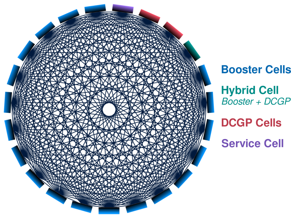
Leonardo features a state-of-the-art interconnect system tailored for high-performance computing (HPC). It delivers low latency and high bandwidth by leveraging NVIDIA Mellanox InfiniBand HDR (High Data Rate) technology, powered by NVIDIA QUANTUM QM8700 Smart Switches, and a Dragonfly+ topology. Below is an overview of its architecture and key features:
- Hierarchical Cell Structure: The system is structured into multiple cells, each comprising a group of interconnected compute nodes.
- Inter-cell Connectivity: As illustrated in the figure below, cells are connected via an all-to-all topology. Each pair of distinct cells is linked by 18 independent connections, each passing through a dedicated Layer 2 (L2) switch. This design ensures high availability and reduces congestion.
- Intra-cell Topology: Inside each cell, a non-blocking two-layer fat-tree topology is used, allowing scalable and efficient intra-cell communication.
- System Composition:
- 19 cells dedicated to the Booster partition.
- 2 cells for the DCGP (Data-Centric General Purpose) partition.
- 1 hybrid cell with both accelerated (36 Booster nodes) and conventional (288 DCGP nodes) compute resources.
- 1 cell allocated for management, storage, and login services.
- Adaptive Routing: The network employs adaptive routing, dynamically optimizing data paths to alleviate congestion and maintain performance under load.

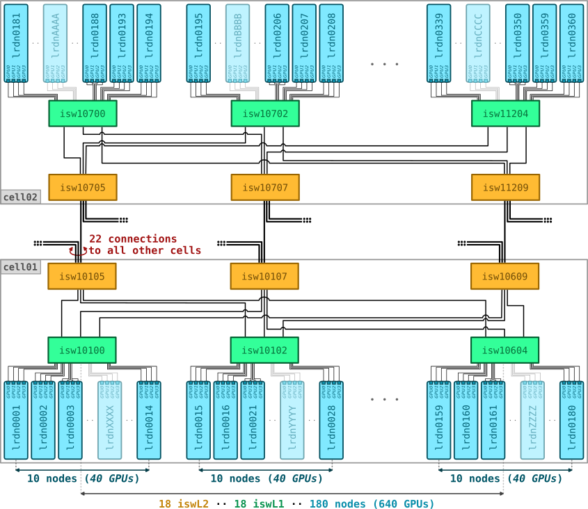
Cell Configuration and Intra-cell Connectivity
Each Booster cell is composed of:
- 6 × Atos BullSequana XH2000 racks, each containing:
- 3 × Level 2 (L2) switches
- 3 × Level 1 (L1) switches
- 30 compute nodes — each equipped with 4 GPUs, each connected via a dedicated 100 Gbps port
Total per Booster cell: 18 L2 switches, 18 L1 switches, and 180 compute nodes.
Connectivity Overview
Level 2 (L2) Switches:
- UP: 22 × 200 Gbps ports connecting to L2 switches in other cells
- DOWN: 18 × 200 Gbps ports connecting to L1 switches within the cell
- Oversubscription: 0.8:1
Level 1 (L1) Switches:
- UP: 18 × 200 Gbps ports connected to all L2 switches in the cell
- DOWN: 40 × 100 Gbps ports connected to GPUs across 10 compute nodes
- Oversubscription: 1.11:1
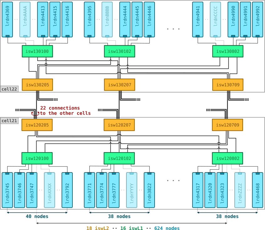
Each DCGP cell is composed of:
- 8 × Atos BullSequana XH2000 racks, each containing:
- 3 or 0 Level 2 (L2) switches
- 2 × Level 1 (L1) switches
- 78 compute nodes — each connected via a dedicated 100 Gbps port
Total per DCGP cell: 18 L2 switches, 16 L1 switches, and 624 compute nodes.
Connectivity Overview
Level 2 (L2) Switches:
- UP: 22 × 200 Gbps ports connecting to L2 switches in other cells
- DOWN: 18 × 200 Gbps ports connecting to L1 switches within the same cell
- Oversubscription ratio: 0.8:1
Level 1 (L1) Switches: (divided into two groups):
- 9 switches with 40 downlinks:
- UP: 18 × 200 Gbps ports connected to all L2 switches in the cell
- DOWN: 40 × 100 Gbps ports connected to compute nodes
- Oversubscription ratio: 1.11:1
- 9 switches with 38 downlinks:
- UP: 18 × 200 Gbps ports connected to all L2 switches in the cell
- DOWN: 38 × 100 Gbps ports connected to compute nodes
- Oversubscription ratio: 1.05:1
Advanced Information
Documents
Article on Leonardo architecture and the technologies adopted for its GPU-accelerated partition: CINECA Supercomputing Centre, SuperComputing Applications and Innovation Department. (2024). “LEONARDO: A Pan-European Pre-Exascale Supercomputer for HPC and AI applications.”, Journal of large-scale research facilities, 8, A186. https://doi.org/10.17815/jlsrf-8-186
Details about new technologies included in the Witley platform with Intel Xeon Icelake contained in the Leonardo pre-exascale system (link)
Additional documents (link)
Some tuning guides for dedicated enviroments (ML/DL or HPC Clusters):
Known Issues
This section collects currently known issues affecting LEONARDO.
The list below is intended as a quick reference for users who may experience problems on the system. We strongly encourage all users to report any issues they encounter - whether listed here or not - to the user support team.